-
Sun, 13/11/2016
-
Thu, 29/09/2016
-
Mon, 05/09/2016
-
Thu, 24/03/2016
-
Tue, 08/03/2016
Department:
Academic year:
2010
Supervisors:
Students:
Alaa Ghassan Osta , Walid Mohamed Zidan
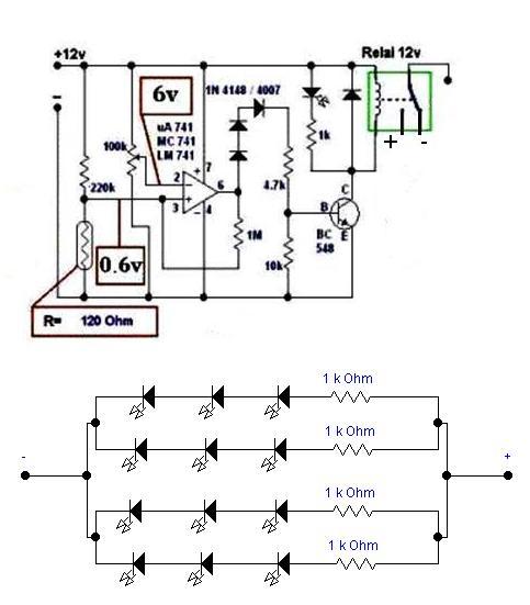
Description of the electronic circuit
We find in the circuit and integrated circuit Lm741 is the vehicle in the circuit in the form of a comparative effort, it compares the constant voltage or a reference No. 2 at the entrance of the effort, variable effort at the entrance to No. 3 The reference voltage is predetermined and this after controlling circuit
We find in the daytime, the voltage at the entrance to No. 3 less effort when the party's No. 2 and this lack of value of resistance light, either way circuit number 6 remains at the logical level 0 and bottom but at night change their minds this contrast more effort at the entrance No. 3 on the effort Entrance 2 to increase the value of resistance, optical, and troubleshooting circuit No. 6 transformed into logical level number 1, meaning the top and this is leading to a feed transistor through diodes three Resistance and 4.7 km to the turn is run relay or ruling to light the lamp that the diodes d 1 d 2 d 3 and put Here the effort to remove the rest, or slightly to the director of circuit No. 6 when the logical state 0 will not be this case does not necessarily equal to zero but may increase it a bit .. The resistance m 4 with a value of 1 megabyte, it helps to take off the circuit immediately when you become the director of the state 0 to state 1 is remove somewhat frequencies resulting from the shift from case to case if for example, if afterward withdraw for popping frequencies in the form of tap of a row when the ruling by the variable resistance can Control in the sensitivity of the circuit and often, or when the circuit design are advised to choose the mid-point can be replaced by the resistance 220 km linked with the resistance value of the optical ones, for example 120 km or 100 km there is nothing wrong in this or that tow resistor replace them with one 47 kg fixed and other variable.